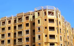
Shear walls are walls specifically designed to resist lateral loads, transferring the load from the wall above to the wall below and, ultimately, out through the foundation. This is a critical role in a building’s structural frame, as walls that do not properly manage lateral loads can experience racking, base shear and overturning.
The Importance of Shear Walls
A stud wall by itself, without bracing such as that provided by wood structural panels, has very little stiffness. When a load is applied, the nail joints between the studs and the top and bottom plates act like hinges, bending easily. The wall could be pushed over at one end with minimal effort, but when a panel-type product is attached, the panel’s ability to resist forces is imparted to the wall.
The ability of a panel to resist loads depends on the physical properties of the panel; the thicker/more rigid each panel is, the more strength the wall gains. Fasteners used to attach the panels to the framing also will affect the lateral resistance of the wall. Closer fastener spacing and larger fastener size will increase wall strength. The sheathing makes the hinge connections rigid and transfers the lateral load through the panel to the bottom of the wall.
An engineer calculates the lateral loads the wall carries to determine the panel thickness, nail size, nail spacing, and other detailing.
What Makes Up a Shear Wall?
Bringing it all together, the shear wall components are:
- Sheathing, which is used the transfer the in-plane force.
- Blocking, which stiffens the wall and increases shear capacity.
- Chords, which are at each end of the wall and are composed of hold downs resisting tension forces when needed and the studs at the end of the wall resisting compression.
Shear walls are limited to an aspect ratio of 3.5:1. A higher aspect ratio typically means higher wall deflection when pushed to capacity. Deflection and stiffness go hand in hand, so this will also matter to force distribution.
Shear Wall Design Methods
The first step in shear wall design for commercial structures starts with determining the loads that need to be resisted. Chapter 16 of International Building Code (IBC) governs the structural design of buildings and refers the designer to ASCE 7 for additional guidance. When an engineer designs a wood shear wall, the primary reference is the Special Design Provisions for Wind and Seismic (SDPWS), which is published in conjunction with the National Design Specification by the American Wood Council.
With wood structural panels, the shear values in SDPWS are a function of fastener size and spacing, panel thickness and grade, and the specific gravity of the framing material. SDPWS Table 4.3A provides nominal unit shear capacities for wood-framed shear walls using wood-based panels.
In the book, there are three methods for designing shear walls: segmented, perforated or force transfer around openings (FTAO).
Segmented
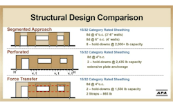
This is the traditional design approach in which only the full-height segments contribute; the panels above and below openings are ignored. The total height of the wall is used to determine the pure aspect ratio, or height-to-width ratio. For example, an 8’ wall with a 4’ panel has an aspect ratio of 2:1. Hold-downs are typically needed at each end of each shear wall segment to resist overturning forces.
Perforated
This empirical design method is based on the percentage of full-height wall segments adjacent to openings. Height and width ratio is again dependent on the total height of the wall over the width of the pier. But unlike segmented shear walls, perforated walls account for the sheathed area above and below openings.
Steel anchors at the base of full-height piers are required to resist both uplift and shear, but hold-downs are only required at each end of the total wall length.
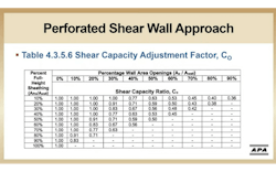
The designer will need to determine the Shear Capacity Adjustment Factor based on the geometry of the wall. In other words, the percentage of full-height sheathing and percentage of wall area openings. This factor reduces the shear wall capacity to account for the impact of the openings and increases the forces for the anchorage and the overturning.
FTAO
Like perforated shear walls, FTAO accounts for the sheathing above and below openings and only places hold downs at the ends of the wall. Straps reinforce the corner of the openings and transfer the tension force into the shear wall. One major advantage of FTAO shear walls is that the height-to-width aspect ratio is dependent on the height of the opening adjacent to the pier, allowing for reduced pier widths to meet the aspect ratio requirements.
Comparing Shear Wall Options
Each of the three shear wall types has its considerations from a structural, architectural, and construction standpoint.
Structurally
Segmented shear walls are a straightforward design, but they don’t capture the strength of sheathing around openings; with limited wall areas to work with, it requires additional hardware. It can be hard to meet the aspect ratios of this design method.
Perforated shear walls are relatively easy to design—you are able to use the capacity of the wall sheathing above and below openings, and it reduces hold-downs. However, designers have to use the full wall height for the aspect ratio. They have to design for uplift at each full-height segment. In addition, some engineers don’t like the empirical basis of the adjustment table.
FTAO walls allow the most design flexibility, with regard to aspect ratio, and provide the narrowest shear walls. This method accounts for the sheathing capacity above and below windows. Fewer hold-downs are required; FTAO may require strapping at opening corners. FTAO is the most complicated design method, but APA – The Engineered Wood Association has a free calculator to help this process.
Architecturally
Shear walls with narrower aspect ratios will allow for more openings and can also be larger.
Shear wall choice also impacts the envelope’s ability to resist moisture and air intrusion.
Constructability
All shear walls utilize wood structural panels, and segments are fully sheathed. They can be installed horizontally, which requires additional blocking at the panel joints, or can be installed vertically, minimizing blocking.
Hold-downs are required to prevent the shear walls from overturning. There are a variety of different types of hold-downs, but the key is they tie the wall down to the foundation or to the wall below, engaging both the wall studs and sill plate or the studs and rim board.
There are several ways to accomplish load transfer with wood structural panels. We can use panels for combined shear and uplift to transfer these forces by butting the wall sheathing over the rim board or by spanning the wall sheathing past the floor cavity. We can also use straps to transfer the uplift forces in conjunction with proper connections to transfer the lateral loads. (For additional design guidance, see APA’s Technical Note E510 and System Report SR101.)
FTAO has additional detailing required in the form of straps when required by the engineer around the openings and blocking on the inside of the wall. Corner straps can be installed on the exterior or interior of the wall. Lumber blocking is installed on the inside of an FTAO wall adjacent to the top and bottom of the opening to transfer compression forces. If you’re installing the corner straps to the inside of the wall, the blocking would need to be flush with the sheathing and the strapping.
A Vital Tool in Building Frames
Wood structural panels play a vital role in keeping walls square and preventing racking. The more sheathing on the walls, the greater the building’s ability to resist wind and earthquakes.
Sheathing also functions as a base for an uninterrupted drainage plane, as a code-approved air barrier material, a continuous nail base for cladding, brick ties and trim materials and a stiffer wall favorable to brittle finishes like stucco and brick veneer.
For more on designing wood shear walls, APA offers several free resources:
- Joint Research Report M410 “Evaluation of Force Transfer Around Openings—Experimental and Analytical Studies”: Outlines information gathered from APA’s shear wall testing that was used to develop design resources. The study was jointly conducted by APA, the USDA FPL and the UBC.
- Technical Note T555 “Design for Force Transfer Around Openings”: Presents the rational analysis for applying the FTAO method to walls with asymmetric piers and walls with multiple openings.
- FTAO Calculator: This Excel-based tool for engineers analyzes shear walls with up to three openings and outputs the shear wall analysis with transparent design equations, a summary of final design requirements and total calculated deflection.
For expanded details on wood shear walls, including wind resistance guidelines/alternatives and extensive visual resources, view APA’s on-demand webinar “Shear Wall Selection for Wood-Framed Buildings.” AIA and ICC CEUs available.


