


Standing on the 10th floor of the sparkling new Ann & Robert H. Lurie Children’s Hospital of Chicago is not exactly a glamorous experience. Compared with walking the hospital’s double-height glass lobby, which features two magical lifesize whale sculptures suspended from the ceiling, or the 11th-floor Crown Sky Garden, with its expansive views of the city and lakefront, the 10th floor seems relatively mundane.
But standing there in the 42-foot-high space talking with the Building Team members that led the construction of the 1.25 million-sf, 288-bed project over a six-year period, it’s easy to see that the two-story mechanical floor is among their greatest sources of pride on the project.
“This floor alone took 10 people 60 hours a week almost seven months to coordinate,” says Peter Rumpf, LEED AP, Integrated Construction Manager with Mortenson Construction (www.mortenson.com). “The level of complexity and the sheer size of the place really challenged the best builders and VDC/BIM users to the limits.”
It’s the perfect example, says Rumpf, of a space that likely could not have been built within the time frame and budget without the use of building information modeling and virtual design and construction coordination. The 60,000-sf mechanical floor required upwards of 12 layers of information—from the structural design to the MEP systems installation to facilities operations considerations—that had to be carefully coordinated in the model.
To execute this effort, the joint construction management team of Mortenson Construction and Power Construction established a BIM operations center, where as many as 40 subcontractors and construction team members were co-located during the project. Prior to coordination meetings, each subcontractor loaded its updated model into Navisworks. The construction management team then integrated the subs’ models and ran clash detection. Clashes deemed significant were discussed and resolved by the entire team. Tens of thousands of coordination issues were resolved virtually, according to Rumpf, a 2012 BD+C “40 under 40” honoree.
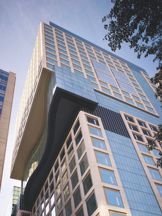
A 12-story cantilever highlights the building’s structural steel design. Beginning at the 11th floor, the building juts out some 15 feet, offering expanded views of the city and lakefront. Using BIM/VDC coordination, the Building Team was able to erect the steel frame in just nine months.
This months-long process of designing then refining in a highly collaborative 3D environment allowed the team to create a true digital prototype of the mechanical spaces. From that prototype, the subcontractors were able to pull installation points and input them into robotic total stations so they could precisely lay out the work as modeled on the project site.
One of the mechanical subcontractors even prefabricated its systems using data from the model to help speed installation and ensure accuracy. All pipe was cut to length and threaded at the firm’s facility nearby and shipped to the site.
“They were able to create work kits,” Rumpf explains. “The team installing the mechanical piping, for example, had a pallet of material that included all the pieces required for that portion of the installation, including hanger rods, unistrut clips, pipe, and insulation.”
While more common today, this level of coordination was virtually unheard of in 2005-06, when the Lurie Children’s project kicked off. “This job changed the Chicago market in terms of BIM capability, because everybody got over the learning curve,” says Eric Hoffman, a former Mortenson Project Manager who joined the hospital as Administrator of Facility Services soon after construction was completed. “The mechanical floor was the absolute critical path on the project.”
BIM O&M coordination
The missing piece in most BIM/VDC-driven building projects is operations and maintenance. For legacy facilities like hospitals, schools, and government buildings, the initial cost of construction may only represent 10-15% of the total cost of ownership.
In a 50- or 100-year facility, something as minor as an incorrectly orientated air handler or a poorly placed ventilation fan can lead to decades of inefficiencies, added costs, and potential safety issues for the owner.

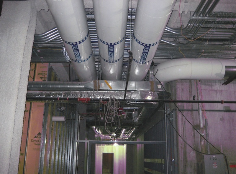
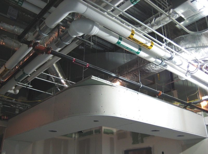
The mechanical floor is so dense with equipment and infrastructure required to service the hospital, the Building Team had to model nearly every element of the space, down to small pipes and conduit, to ensure efficient and accurate installation.
To date, few BIM/VDC projects have involved facilities personnel at a deep level. The Building Team for the Lurie Children’s project was one of the early pioneers in this area. During both the design and preconstruction phases, the design and construction teams met with the operations staff to get a better understanding of their processes and procedures and the type of data required for operating and maintaining the building’s equipment. These meetings led to early design decisions that will allow the operations staff to more efficiently service the facility.
“There are numerous opportunities on the front end, looking at the model, to do some facilities-oriented solutions,” says Hoffman. “The designer or engineer may think they need this type of fan, but the facilities person is thinking, ‘To service this piece of equipment, I have to pull it out a certain way and it weighs 150 pounds, so how do I get it out and down safely?’ These are the kinds of exercises the team can do on the front end that can make the difference between 50 years of a bad design or a design that is efficient, easy, and safe.”
A prime example at the Lurie Children’s tower is the access pathways designed into the mechanical room that allow the facilities team to service the equipment and perform regular inspections.
“See that ladder right there?” Rumpf asked during a tour of the facility, pointing to a small steel ladder bolted to the wall that leads up between two massive ducts. “That’s part of our ‘chutes and ladders’ exercise.” Because the mechanical floor is so dense with equipment and infrastructure, the Building Team had to devise pathways for facilities personnel and fire/life safety inspectors to reach critical areas, such as fire sprinkler heads and smoke dampers.
Rumpf admits that some of the access solutions are not all that elegant, but they’re effective in helping the operations team service the space. For instance, the ladder leads to a smoke damper 40 feet overhead and obscured by layers of ductwork. Every six years, the damper must be inspected to ensure it’s working properly. To reach it, a facilities staffer must climb the ladder, transition across an air-handling unit, open up an access zone inside a 12-foot-wide duct, step into the duct, open a door on the other side of the duct, step out onto a platform, and climb up another ladder.
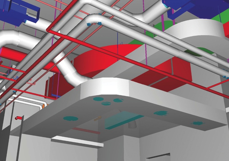
Two-dimensional drawings of the mechanical space proved ineffective in communicating what was required to get all the systems built and installed properly, so the team utilized 3D BIM model views. Views of the coordination model were plotted out and referenced by the mechanical contractors during the build.
“It was an extreme challenge for us to fit all the systems together and get them to work together and then layer back how we were going to service this space,” says Rumpf. “I don’t know how it would have been done without 3D BIM coordination. A smoke damper like that may have been ignored in the past.”
The team also devised a tie-off system of aircraft cables embedded in the slab above the space that is useful for both construction and O&M. To ensure the safety of the users, the team utilized the model to determine the optimal location of the tie-off points so that a person is no farther than 10 feet from a tie-off point at any given time.
Tracking progress with laser scanning
Because no two floors in the hospital are the same, measuring and improving the construction progress from floor to floor proved difficult.
“It’s not like a hotel, where we can track how long it took to build the first five floors and come up with ways to build the remaining floors faster,” says Rumpf. “We didn’t have the luxury of repetition.”
To validate its MEP systems installation processes, the team utilized laser scanners to create a point cloud model of the installed systems. The data was then inputted into Navisworks, where the team could visually inspect the difference between the construction BIM model and the digital representation of reality. By continually measuring the delta between the real world and the digital model, they were able to quickly recognize any disconnects.
Rumpf cites the building’s pneumatic tube system as an example: “The person who was creating the model was using shapes and bends that would not allow the containers carrying medical samples and supplies to get from point A to point B in the specified time. The installer knew that to meet the performance specification the tube system could not have too many bends and made the necessary adjustments in the field. As a result, the radiuses in the model were different from those installed. Because of the laser scanning and BIM analysis, we were able to catch this early on and have the installer review and sign off on the altered design before installation drawings were produced.”
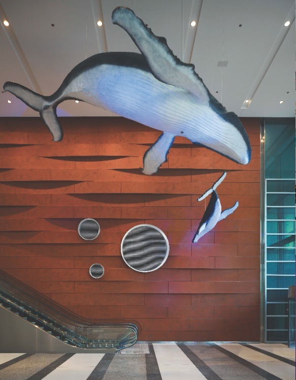

The two whale sculptures suspended from the lobby ceiling (top) were donated to Lurie Children’s when the project was about 85% complete. To accommodate the massive pieces spatially and structurally, the team laser scanned the whales to determine their size and scale (bottom).
The Building Team also used laser scanning to capture the geometries of the whale sculptures in the lobby, which were donated by the Shedd Aquarium when construction was 85% complete. The mother and calf were in a half dozen pieces in the basement of the Field Museum. The team placed each piece on tripods, laser scanned them, and then stitched together the scans to create a complete picture of the sculpture. The point cloud information was used to create an accurate digital model, which the architectural and structural teams used to spatially orient and support the whales. The installation required both structural reinforcement and rigging, all while the project was nearing completion.
“Could we have done it without the 3D model coordination? Probably,” says Rumpf. “But it would have cost more, and there probably would have been some modifications to the end product. We were able to accomplish this with very few concessions to the design intent, and the schedule was not impacted at all.”
PROJECT SUMMARY
Ann & Robert H. Lurie Children’s Hospital of Chicago
Chicago, Ill.
Size: 1.25 million sf
Construction cost (excluding land): $605 million
Completed: June 2012
Floors: 23
BUILDING TEAM
Owner: Ann & Robert H. Lurie Children’s Hospital of Chicago
Architects: ZGF Architects LLP; Solomon Cordwell Buenz; Anderson Mikos Architects
Structural engineer: Magnusson Klemencic Associates
MEP engineer: Affiliated Engineers
Construction managers: Mortenson Construction, Power Construction (joint venture)
Lurie Children’s Hospital BIM/VDC Execution Plan
PRECONSTRUCTION PHASE
BIM Protocol Manual
• Entire project team co-located for two days to create the roadmap for how technology was going to be leveraged on the project.
• Buy-in from all parties: owner, design team, and construction team.
Life Cycle Analysis
• Contractor and architect met with the owner’s operations team to create a list of data needed for the maintenance/operation of the equipment (serial number, manufacturer, warranty start date, etc.).
• Evaluated opportunities to leverage BIM to add value to the current operations team’s processes and procedures.
Subcontractor Evaluation
• Contractor evaluated the BIM capabilities of the preferred subcontractors using a trial model exercise, where prospective subs were required to submit examples of their model data. The contractor also visited the subs’ offices to assess their BIM departments.
DESIGN PHASE
Design Phase Coordination
• Contractor was embedded with the design team to provide constructability review and real-time cost analysis, and assist in coordination of consultant models.
Life Cycle Analysis
• Design team added data fields to the design intent model that corresponded to the list generated by the operations team. The goal was to create a BIM model that was durable enough to support design, construction, and operations.
Design Model Review
• Regularly scheduled design model review sessions allowed all consultants to visualize the spaces.
CONSTRUCTION PHASE
On-site Setup
• All subcontractors were co-located in the same building as the owner and design team.
• Local server established for all team members to allow efficient file transfers.
• The contractor leveraged proven coordination processes, coordination protocols, and file standards.
Prefabrication
• Contractor held an initial prefabrication meeting with subcontractors prior to coordination kickoff to identify prefabrication opportunities.
• All subcontractors prefabricated their work for efficient installation in the field.
Installation/Layout
• Robotic Total Station (Trimble) was leveraged to ensure that the digital prototype was followed in the field. Layout points were fed directly from the digital prototype to the station.
• Quality engineers used tablet PCs to ensure proper installation.
OPERATIONS PHASE
Testing and Balancing
• Project team was enabled with field hardware (iPad and Samsung Series 7 tablets) to leverage BIM in field software platforms (Vela) and streamline testing and balancing.
• Punchlist was streamlined using the iPad and Vela software.
Facilities Management
• Part of the turnover process included a model review of the access zones for major equipment.
• Key success factor was creating animations of the access path to obscured equipment for reference by the operations team.
Related Stories

MFPRO+ News | Dec 11, 2023
U.S. poorly prepared to house growing number of older adults
The U.S. is ill-prepared to provide adequate housing for the growing ranks of older people, according to a report from Harvard University’s Joint Center for Housing Studies. Over the next decade, the U.S. population older than 75 will increase by 45%, growing from 17 million to nearly 25 million, with many expected to struggle financially.

Office Buildings | Dec 11, 2023
Believe it or not, there could be a shortage of office space in the years ahead
With work-from-home firmly established, many real estate analysts predict a dramatic reduction in office space leasing and plummeting property values. But the high-end of the office segment might actually be headed for a shortage, according to real estate intelligence company CoStar Group.

University Buildings | Dec 8, 2023
Yale University breaks ground on nation's largest Living Building student housing complex
A groundbreaking on Oct. 11 kicked off a project aiming to construct the largest Living Building Challenge-certified residence on a university campus. The Living Village, a 45,000 sf home for Yale University Divinity School graduate students, “will make an ecological statement about the need to build in harmony with the natural world while training students to become ‘apostles of the environment’,” according to Bruner/Cott, which is leading the design team that includes Höweler + Yoon Architecture and Andropogon Associates.

University Buildings | Dec 5, 2023
The University of Cincinnati builds its largest classroom building to serve its largest college
The University of Cincinnati’s recently completed Clifton Court Hall unifies the school’s social science programs into a multidisciplinary research and education facility. The 185,400-sf structure is the university’s largest classroom building, serving its largest college, the College of Arts and Sciences.

MFPRO+ News | Dec 5, 2023
DOE's Zero Energy Ready Home Multifamily Version 2 released
The U.S. Department of Energy has released Zero Energy Ready Home Multifamily Version 2. The latest version of the certification program increases energy efficiency and performance levels, adds electric readiness, and makes compliance pathways and the certification process more consistent with the ENERGY STAR Multifamily New Construction (ESMFNC) program.

Architects | Dec 5, 2023
Populous celebrates its 40th anniversary with a photo exhibit of its works
The firm partnered with Getty Images to assemble more than 60 images, many capturing fan ardor.

Office Buildings | Dec 1, 2023
Amazon office building doubles as emergency housing for Seattle families
The unusual location for services of this kind serves over 300 people per day. Mary's Place spreads across eight of the office's floors—all designed by Graphite—testing the status quo for its experimental approach to homelessness support.

Mixed-Use | Nov 29, 2023
Mixed-use community benefits from city amenities and ‘micro units’
Salt Lake City, Utah, is home to a new mixed-use residential community that benefits from transit-oriented zoning and cleverly designed multifamily units.

Giants 400 | Nov 28, 2023
Top 100 Laboratory Design Firms for 2023
HDR, Flad Architects, DGA, Elkus Manfredi Architects, and Gensler top BD+C's ranking of the nation's largest laboratory architecture and architecture/engineering (AE) firms for 2023, as reported in Building Design+Construction's 2023 Giants 400 Report.

Engineers | Nov 27, 2023
Kimley-Horn eliminates the guesswork of electric vehicle charger site selection
Private businesses and governments can now choose their new electric vehicle (EV) charger locations with data-driven precision. Kimley-Horn, the national engineering, planning, and design consulting firm, today launched TREDLite EV, a cloud-based tool that helps organizations develop and optimize their EV charger deployment strategies based on the organization’s unique priorities.


