The Role of Diaphragms and Shear Walls in Creating Resilient Structures
When designing a building for lateral loads such as those generated by wind or earthquakes, engineers have several options. Lateral loads may be transferred to the foundation via braced frames or moment frames; diagonal rods, or flat diagonal bracing (including let-in bracing for wood frame construction), among other methods. Where wood structural panels are used for the roof, floors or walls in a building, lateral loads can be resisted using these ordinary wall elements. This type of construction is adaptable to conventional wood-frame construction used in residences, apartment buildings and offices. Buildings can be designed to resist the horizontal loads introduced by extreme wind or earthquakes by applying diaphragm design principles to your walls, floors and roofs.
Here is an overview of diaphragms and shear walls and how they can be incorporated into the design of your next building project.
Diaphragms and Shear Walls Defined
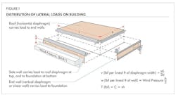
A diaphragm is a flat structural unit acting like a deep, thin beam. The term “diaphragm” is usually applied to roofs and floors. A shear wall, however, is a vertical, cantilevered diaphragm. A lateral building system results when a series of vertical and horizontal diaphragms are properly tied together to form a structurally stable unit. (See Figure 1.) When diaphragms and shear walls are used in the lateral design of a building, the structural system is termed a “bearing wall lateral system.” Shear walls transfer reactions from the roof and floor diaphragms and send the forces into the foundation. An accurate method for engineering diaphragms has evolved from analytic models and extensive testing. It allows engineers to supply clients with a building resistant to severe weather conditions and seismic activity at little cost.
The structural design of buildings using diaphragms is a straightforward process if engineers consider the overall concept of structural diaphragm behavior. With ordinary good construction practice, any sheathed element in a building adds considerable strength to the structure. So, if the walls and roof are sheathed with panels and adequately tied together and to the foundation, many of the requirements of a diaphragm structure are met. This explains the durability of panel-sheathed buildings in hurricane and earthquake conditions — even when they have not been engineered as diaphragms. For full diaphragm design, it is also necessary to analyze chord stresses, connections and tie-downs.
Panel diaphragms have been used extensively for roofs, walls, floors and partitions for new construction and rehabilitation of older buildings. A diaphragm acts like a deep beam or girder, where the panels act as a “web,” resisting shear, while the diaphragm edge members perform the function of “flanges,” resisting bending stresses. These edge members are commonly called “chords” in diaphragm design and may be joists, ledgers, trusses, bond beams, studs, top plates, etc.
A shear wall is simply a cantilevered diaphragm to which load is applied at the top of the wall and that load is transmitted out along the bottom of the wall. This creates a potential for overturning, which must be accounted for. Any overturning force is typically resisted by hold-downs or tie-downs at each end of the shear element.
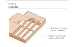
Diaphragms vary considerably in load-carrying capacity, depending on whether they are “blocked” or “unblocked.” Blocking consists of lightweight framing, usually 2x4s, spanning between the joists or other primary structural framing to support the edges of the panels (See Figure 2). Systems that provide support framing at all panel edges, such as panelized roofs, are also considered blocked. Another form of blocking for purposes of shear transfer is with metal framing screwed to adjacent panels to provide shear transfer between panels. Unblocked diaphragm loads are controlled by buckling of unsupported panel edges, resulting in such units reaching a maximum load above which increased nailing will not increase capacity. For the same nail spacing, design loads on a blocked diaphragm are 1 1/2 to 2 times the design loads of unblocked counterparts. In addition, the maximum loads for which a blocked diaphragm can be designed are many times greater than those for diaphragms without blocking.
The four major parts of a diaphragm are the web, chords, collectors and connections. Since the individual pieces of the web must be connected to work as a unit, connections are critical to good diaphragm action. Their choice becomes a major part of the design procedure.
Advantages of Wood Diaphragm Design
Structural wood panel diaphragms take advantage of the capacity of wood to resist sudden and cyclic loads. They maintain high strength in the design range and, if pushed to their ultimate capacity, yield gradually while continuing to carry the load. By considering the strength and stiffness of the skin of a building, engineers can eliminate almost all expensive and inefficient diagonal bracing, which might otherwise be required. Wood diaphragms are easy to build and connect to other portions of the structure. The primary components of the system are structural panels, structural lumber, nails and metal connectors.
Panel diaphragm design has been proven through some of the most extreme weather and seismic events. Wood lateral systems enable engineers to produce a building designed to resist high wind and seismic loads for little or no extra cost.
Find more information on diaphragms and shear walls on APA’s website, including a new on-demand webinar: “Designing Engineered Wood Diaphragm Systems.” Learn best practices as you’re guided through simple design examples by one of APA’s Engineered Wood Specialists.
For more in-depth guidance, download APA’s free Diaphragms and Shear Walls Design and Construction Guide. This 37-page publication contains numerous design examples, illustrations and formulas for calculating deflection and other critical details.


