Air barriers: Expectations vs. reality
When it comes to building performance, too much of a good thing can become a bad thing. Humidification to provide medical patient comfort is a good thing. Frost and ice damage due to that same humidification is not so good.
When new building code requirements require high performance and innovation incentives, such as those found in green building rating systems, significant confusion and some building failure will ensue. This is the current situation that designers and contractors are facing in wall system air barrier design and performance. Overly complex and problematic exterior wall systems due to a market-driven design emphasis on energy savings, high performance, and innovation inevitably lead to increased risk and liability in all climates, and concern about mold and moisture damage in hot/humid climates.
Significant in 2012 was the issuance of the International Green Construction Code (IgCC). This provided a vehicle for codifying many elements of the U.S. Green Building Council (USGBC) Leadership in Energy & Environmental Design (LEED)® rating systems and ASHRAE standards that have been issued over the last decade. (Most of them have been released in just the last two years.)
The development of codes such as the IgCC are often based on collaboration through cooperating industry professional society sponsors. Despite the benefits of collaboration, high performance and innovation initiatives are often driven by code empirical laboratory analysis, which sometimes does not translate well to field applications. This codification is then pushed out to contractors, who unfortunately must then face the task of interpreting sometimes puzzling requirements that don’t always make sense or work in the field.
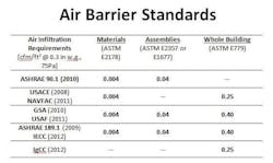
Conscientious designers and contractors tend to be more familiar with qualitative testing (such as visual inspections) as a means to determine if an air barrier is continuous and visually leak-free. However, it is the air leak that is not visual that is important. Demonstrating and validating air barrier performance by using quantitative testing methods (such as field testing for compliance with air infiltration requirements) in order to comply with new codes and standards (Figure 1) is new and less familiar to designers and contractors. The difficulty for them is in understanding what the numbers mean, interpreting different results, and tightening the performance of what they can’t see. They know how to design and build a successful building using tried and true methods, but when mandated to use new products or methods to achieve high performance or accreditation, they have no track record or field studies to fall back on.
Figure 1: Air Barrier Standards where the air infiltration requirements for each component are written based on ASTM standards for that component and verified through field testing. The left hand column is comprised of various codes and standards. Note the emphasis that the IgCC and the United States Army Corps of Engineers (USACE) has placed on high performance and innovation by driving more stringent whole building air infiltration requirements from 0.40 CFM per SF to 0.25 CFM per SF.
Because designers are often unfamiliar with air barrier and HVAC dynamics, our firm, Liberty Building Forensics Group (Liberty), has been called upon on numerous occasions to resolve moisture and mold issues that arise as a result.
The following case study presents an example of what we encountered when excessive humidification, building positive pressurization, and a leaky building envelope combined to cause condensation, frost, and ice damage in a Midwestern medical facility. Liberty was called in two years after construction to determine the most effective and least disruptive resolution to the now fully functioning facility’s problem. The designer had not properly specified an air barrier for the building, which led to the leaky envelope condition. These problems could have been avoided if the designer had specified proper materials, installation, and testing for the air barrier system.
Case Study--Humidification, Pressurization, and Air Leaks Cause Frost and Ice Damage to a Medical Facility
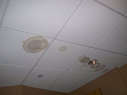
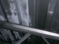
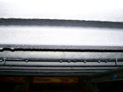
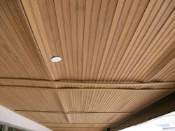
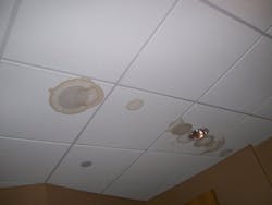
A 50-bed medical facility located in the Midwest experienced buildup of frost and ice in above-ceiling spaces, soffits, and in clerestories during winter months two years after construction was completed in 2006. The frost/ice (Figure 2a) would eventually melt (Figure 2b), wetting the ceiling surfaces, causing damage (Figures 3a and 3b), and leaking into the occupied rooms below. The facility owner and designer originally attributed the frost and ice buildup to an improperly installed air barrier system. While the presumptive “air barrier” was in fact not tight, an investigation also revealed the following:
- The designer had specified exterior wall materials that were not capable of providing a tight air barrier.
- The building heating, ventilating, and air-conditioning (HVAC) system contained humidifiers for patient comfort during the winter. These humidifiers were improperly operating and were set too high, causing excess humidity that led to the buildup of frost and ice in concealed cold spaces.
- Building pressurization, as designed (based on interpretation of state regulations), played a role in pushing the humid interior air past the air barriers and into colder concealed spaces (exfiltration), where it condensed on cold surfaces and formed frost and ice.
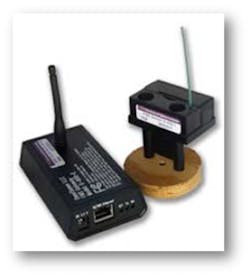
Internet-connected wireless data loggers were used to show how properly operating the humidifiers without sacrificing occupant comfort solved the frost/ice problem.
Figure 3b: Damage to ceiling tiles due to melting frost/ice in above-ceiling space.
As-Built Conditions In Accordance With Design
The exterior walls of the steel-framed building were finished with stucco (portland cement plaster) on gypsum sheathing attached to metal studs. A polyethylene vapor retarder was specified and installed. Although some gaps and loose sealing tape were observed in the vapor barrier, overall installation of the material was good when compared to the requirements of a functional vapor retarder, which does not require an airtight seal.
The polyethylene vapor retarder with taped joints was a poor design choice if the design team expected the vapor retarder to function as an air barrier. The use of taped joints on unbacked sheet membrane is considered a poor industry practice for air barriers. Additionally, the design did not provide for tying the wall barrier into the roof system to form airtight construction. The design specifications referred to the polyethylene sheeting as a vapor retarder and not an air barrier. The specifications did not mention air barrier nor provide air barrier performance criteria. The only hint was a vague specification reference to sealing joints at penetrations with vapor retarder tape to “create an airtight seal.”
Two humidifiers had been installed within the facility’s HVAC system. It was found that they were being operated in a manner that allowed wintertime interior RH to vary greatly from 30% to above 50%. Humidity sensors in the ductwork had also been located by design in a place that did not allow for accurate readings and control.
The building pressurization had been designed to be positive relative to outdoors (more outdoor air introduced into the building through the HVAC system than was exhausted) based on the design team’s interpretation of state regulations for this type of facility. This was contrary to industry knowledge (including ASHRAE) that in cold winter heating climates, neutral to slightly negative pressurization is desirable, especially for buildings that contain humidifiers. A review of state regulations revealed that the exterior patient rooms could be kept neutral relative to outdoors, as recommended by the industry, and still meet the regulation requirements.
After frost and ice problems began to show up, attempts were made to seal up the above-ceiling spaces and soffits by applying spray foam insulation in the exterior soffits at the exterior wall line. This approach did not appear to have any significant effect on reducing the problem.
Humidification Testing and Analysis
Through quantitative analysis, it was determined that proper operation of the humidification system would solve the frost/ice problem without changing pressurization and/or replacing/altering the presumptive “air barrier.” Replacing/altering the specified vapor retarder to act as an air barrier would have required tear-out of finish materials and disruption of this fully-operational facility.
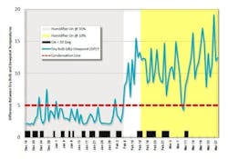
To prove the efficacy of the recommended humidification fix, 69 wireless data loggers were installed in the concealed spaces, occupied rooms, HVAC system, and outdoor air (Figure 4). These data loggers recorded dry-bulb temperatures and relative humidity (RH), which were then monitored in real-time via the internet. Dew point temperatures were calculated from this information and subtracted from dry-bulb temperatures. To avoid condensation, this temperature difference needs to be five degrees Fahrenheit (ºF) or greater.
During the datalogging test period, the humidifiers were first run at 35%, then turned off, and then put at the lowest setting. Results from the datalogging showed that operating the humidifier at 35% RH during winter resulted in increased risk of condensation and frost/ice formation (Figure 5). This setpoint of 35% RH (and sometimes higher) was what the owner had been using when condensation problems had occurred. This is a very high interior RH for northern climates in the winter and has been shown to result in moisture and mold problems in facilities that have humidifiers, such as museums.
When the humidifier was set to its lowest setting (reported by the owner to be 10% RH), the risk of condensation and ice decreased dramatically (Figure 5). No condensation, frost, ice, or water leaks were reported during this period. The design team was concerned that the lowest humidifier setting would result in occupant dryness complaints, but no such complaints occurred during the test period. Additionally, as had been predicted, the actual room RH averaged 25% at the lowest setting (not 10%), which was in the range that had been suggested and to which the design team agreed if occupants did not complain (Figure 6).
Figure 5: Chart of difference between dry-bulb and dew point temperatures in Soffit SF, from Dec. 16, 2008 through March 28, 2009. With humidifiers on and set to provide 35% RH (grey area in left side of chart), the difference (blue line) was below or close to five (red dotted line) which increased the risk for condensation and ice formation. With the humidifier off (white area in middle of chart) or on and set at 10% RH (yellow area in right side of chart), the differences were generally above 5, decreasing the risk for condensation and ice formation.
Figure 6: Occupied room RH measurements during the various humidifier settings. Note that with the humidifier set at its lowest setting (assumed by owner to be 10%), the RH averaged 25% was only below 20% three percent of the time.
Conclusions
Datalogging proved that correcting one (humidification) of the three issues causing condensation (gaps in the presumptive “air barrier”, pressurization, humidification) solved the problem. It was recommended that the conditions be monitored for another year. If the condensation re-occurred, then the next step would be to adjust the building pressurization to neutral or slightly negative.
Fortunately, condensation did not re-occur after the humidification system was altered. The alterations to the humidification system included:
- Placement of RH sensors controlling the humidifiers in the occupied space to provide better control of building RH.
- Setting the wintertime target RH at 20% to 25%.
- Preventing the controls from allowing settings above 35%.
- Training onsite maintenance personnel in proper operation of the humidification system.
The data loggers were left in place for use by the owner to monitor the efficacy of the humidification system alterations. During initial monitoring of the data loggers, internet access to information they were sending was granted to all involved parties, including contractors, designers, and the owner. Because of this, the owner was already set up to monitor the data after the consulting scope was complete. The batteries in these data loggers have a 15-year life, so the owner will not need to access them and will continue to receive data for that period of time.
When it comes to building failures, problem avoidance is always the best course of action to take. This requires a proactive peer review process that balances any attempts to achieve high performance through innovation with adherence to code regulation that is backed up by extensive quantitative analysis. This medical facility, while not necessarily “green,” combined several complex factors found in high-performance buildings, including added humidification and designed pressurization. A peer review focusing on the interaction between the HVAC system and building envelope would have revealed the problems during design phase, allowing them to be corrected before construction.
Liberty Building Forensics Group is committed to SOLVE. FIX. PREVENT. RECOVER the world’s most complex building mold and moisture failures. Our firm has project experience in the U.S., Canada, Mexico, the Caribbean, Central America, the Middle East, Southeast Asia, and Europe. Contact us at [email protected] or by phone at 407/467-5518 or visit us at http://www.buildingforensicsgroup.com/.
