Advanced laser scanning technology supports data collection and modeling efforts for Missouri’s Iatan 1 Power Plant
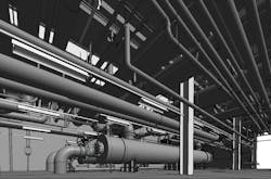
When the power division of Black & Veatch needed to perform field measurement and modeling of the complex Iatan 1 Power Plant, located near Platte City, Missouri, they engaged Structural Modeling & Analysis (SMA), a Kansas City-based firm specializing in structural engineering design and analysis as well as laser scanning and modeling. SMA was brought in at the urging of Kansas City Power & Light Company (KCP&L) in order to save time and money while navigating the unique challenges created by a pipe-dense plant. The job entailed laser scanning the site to collect all the data, registering, making a model showing all the piping in Autodesk® Revit® and exporting it out in AutoCAD® to deliver results, enabling the safe and successful installation of a new heat exchanger.
Challenges
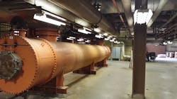
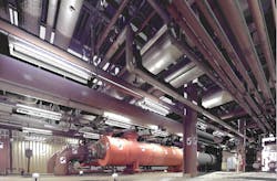
Black & Veatch, a large engineering, procurement and construction (EPC) company, understood the complexities of the 651-megawatt (MW) Iatan 1 Power Plant site, including the quantity and density of the piping as well as how little room for error existed due to all the piping connections required between the existing heat exchangers and the new one they wanted to install. Black & Veatch did not, however, have much experience in laser scanning, therefore, SMA Engineering was contracted to conduct the condition survey of the plant.
Due to the tremendously complex, pipe-dense space, the engineer’s plan initially budgeted six to eight weeks for field measurement and approximately 10 additional weeks for modeling the information from the field. In addition to the inordinate amount of time they were looking at, another concern was accuracy: trying to measure a space that was approximately 100 feet long by 50 feet wide, with two floor levels, three levels of cable trays and 2,000 pipes is a daunting task if using traditional methods such as tape measures and standard field measurement practice.
Safety and workflow at the power plant were among the other major challenges with this project. According to J Brown, P.E., S.E., Principal Engineer at SMA, “Given the multiple floors and dense piping, the safety of those performing the work would be of utmost concern. Utilizing traditional measuring methods, there would be little chance to safely access all the spaces required.” Another concern was how not to interrupt the workflow of the location, something that is critical at an active power plant.
Solutions
Time
With their expertise in utilizing laser scanner technology and modeling, the SMA team went into the space and performed a total of 93 scans using the FARO Focus3D X 330 Laser Scanner, in just 12 hours—a day and a half of work.
Prior to leaving the site, SMA began registering the scans and checking to confirm they had sufficient data to accurately model the cable tray, piping and equipment. In addition, they performed their confirmation process to back-check the scan data to the real world.
Brown explains the process further: “Once back in the office, the processing and registration was completed using SCENE, FARO’s 3D documentation software. At that point, the scan data was run through Autodesk® ReCap 360™ to create the files for use with Autodesk® Revit®. Then, we used Trimble EdgeWise to very rapidly convert the laser-scanned pipes into Revit® component pipes. We used EdgeWise to model the pipes and perform the rest of the modeling within Revit®, thereby extending the usefulness of the point cloud.”
While there was a fair amount of tweaking to account for some false positives, the software did an excellent job in terms of being able to get a very large amount of data switched over. This aspect of the job took another three weeks, followed by another two and a half weeks for cleanup, finishing, connecting pipe elbows, etc.
So, while Black & Veatch originally estimated spending six to eight weeks on field measuring alone, and an additional 10 weeks for modeling, SMA was able to accommodate a much shorter window. Mark Middleton, SMA’s Business Development Manager adds, “After the scanning, SMA modeled all of that piping—over 2,000 pipes, three levels of cable tray, two giant heat exchangers and a mezzanine level and ground level floor space. With the scanning technology in place, we were able to scan, register and model everything in only five and a half weeks total.”
Safety and Accessibility
Due to the portability of the scanner vs. a more traditional method, the risk factors on the job were minimized—for instance, the mobility to safely take the system up a set of stairs. On the second level, for example, the KCP&L team lifted a grate, allowing SMA to flip the scanner upside down, shoot it down into the hole and then shoot it all the way down the cable tray. Brown notes, “It would have been physically impossible, not to mention a huge safety issue, to actually climb out on those pipes. Therefore, using the scanner enabled us to access the 2,000 pipes, most of which we would not have been able to get to using traditional field measure protocols. We were able to scan the top surface and the underside because we were able to flip the laser scanner upside down.”
SMA was able to perform the work from ground level (either the floor or the mezzanine platform) instead of using a scissor lift or scaffolding—or just not being able to get the data at all.
Bottom line, laser scanning allowed the team to capture areas that would otherwise be too dangerous, impractical, or impossible to document with a tape measure or traditional methods of field measurements.
Accuracy
Being able to scan and collect data from both the top surface and underside allowed SMA to establish the pipes’ outer diameters with much greater accuracy since they essentially had access to the entire cross section. If they only had the bottom side, for instance, they would have just gotten portions and the software would have had a much harder time assigning pipe diameters. (Note: since most of the pipes were insulated, only the outer diameters could be measured.)
SMA was able to model the existing heat exchangers and showed the space available for the new exchanger. The model accurately located all of the pipes, cable tray, lighting, etc. that new lines for the new heat exchanger would have to be routed around and/or identified existing lines that would have to be re-routed.
Workflow
Using the eye-safe FARO Focus3D X 330 allowed SMA to work without endangering the employees or causing a disruption to the normal plant operation. J Brown notes, “The unobtrusive nature of the scanner resulted in no interruption to workflow, a critical factor for the functioning of a power plant. There was no need to section off any areas for the team. The plant was operating while they were working and there were adjacent KCP&L employees working in the area as well.”
Results
Deliverable
SMA modeled the site in Revit® and then exported it out in AutoCAD®, which is what the client required.
Time savings
The client estimated six to eight weeks of field measurements and 10 weeks of modeling to convert those measurements to the required AutoCAD® model. Creating an as-built condition survey with a laser scanner, a 16- to 18-week project was minimized to just over five weeks total, saving a total of 13 weeks from the worst-case projection.
Cost savings/ROI
The client charged approximately $180/hr x 2 people in field + 3 people doing design work. SMA estimates that they saved the project approximately $80,000 based on what they were initially told the field measurements and modeling would cost.
Conclusion
As stated on the SMA website, “When you consider the cost of sending a team to be on site for days or weeks to gather a few hundred to a thousand measurements using traditional methods—and compare it to being on site for a fraction of that time and picking up millions if not billions of measurements—the cost of laser scanning pays for itself.”


