Thirteen structural steel building projects have earned national recognition in the 2013 Innovative Design in Engineering and Architecture with Structural Steel awards program (IDEAS2). Conducted annually by the American Institute of Steel.
Construction (AISC), the IDEAS2 awards recognize outstanding achievements in engineering and architecture on steel-framed building projects throughout the U.S. The award is the highest honor bestowed on building projects by the structural steel industry in the U.S. and recognizes the importance of teamwork, coordination and collaboration in fostering successful construction projects.
The winning projects and their respective team members were recognized on April 17 during AISC's 2013 NASCC: The Steel Conference in St. Louis. Each year, awards for each winning project are presented to the project team members involved in the design and construction of the structural framing system, including the architect, structural engineer, general contractor, detailer, fabricator, erector and owner.
A panel of design and construction industry professionals identified National and Merit winners in three categories, based on constructed value: projects less than $15 million; projects $15 million to $75 million; and projects greater than $75 million. In addition, the panel awarded a Presidential Award of Excellence in Engineering to one project for structural engineering accomplishment.
The 2013 award-winning projects are (photos and project descriptions courtesy AISC):
Projects Greater than $75 Million
NATIONAL AWARD
NASCAR Hall of Fame, Charlotte, N.C.
Building Team
Owner/Developer: City of Charlotte; NASCAR Hall of Fame, Charlotte, N.C.
Owner’s Representative: NASCAR, Charlotte, N.C.
Architect: Pei Cobb Freed & Partners LLP, New York
Architect: Little Diversified Architectural Consulting, Charlotte, N.C.
Structural Engineer: Leslie E. Robertson Associates, RLLP, New York
General Contractor: BE&K Building Group, Charlotte, N.C.
Steel Fabricator: SteelFab, Inc., Charlotte, N.C.
Steel Detailer: Hutchins & Associates, Clemmons, N.C.
Steel Erector: Williams Erection Company, Smyrna, Ga.
Bender/Roller: SteelFab, Inc., Charlotte, N.C.
Design-Build Contractor for Ribbon: Zahner, Kansas City, Mo.
Consultant: Ralph Appelbaum Associates, Inc., New York
Consultant: Jaros Baum & Bolles, New York
Photograph: Paul Warchol Photography Inc.
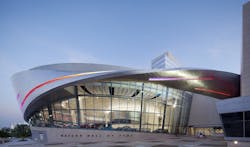
In approaching the challenge of designing a Hall of Fame for NASCAR, the project’s design team sought to capture the essential spirit of NASCAR and its sport in architectural form. In exploring the possibilities for expressing speed and spectacle, the team was drawn to the arena of action, the racecourse, where fans and race teams come together each race week for the spectacle of race day.
Curving, sloped forms are evocative not only of the dynamic and changing sinuous shape of the racetrack but also of the perception of speed, which is at the heart of the NASCAR spectacle.
The expression of these forms could only have been achieved through the use of steel, as cladding and as structure, encompassing several long-span elements, architecturally exposed structural steel (AESS) elements, and employing innovative approaches to connections, steel detailing, and the interface of structural steel with stone, glass, and steel as a finish material.
The Hall of Fame consists of four basic elements:
• A large glazed oval shape forming a Great Hall serves as the symbolic core of the Hall of Fame.
• A rectangular volume houses visitor services, including entry and exhibit space on upper floors.
• An expressed Hall of Honor is situated as an iconic element within the Great Hall.
• A broadcast studio enlivens the Hall of Fame Plaza, the sweeping forecourt that welcomes visitors.
The results of the teams’ explorations of speed and spectacle evolved into an architectural element - the Ribbon - 5,000 stainless steel panels that envelope the full-block building in a form that speaks to the imagery and spirit of NASCAR. Made of stainless steel in a lustrous angel-hair finish that softly reflects light and accentuates its dynamic aspect, the Ribbon is a sculpted form that changes as it wraps around the building.
Within the Great Hall, a signature element of a curved banked ramp leads the visitor from the main floor to exhibit levels above. The ramp contains a display of race cars frozen in a moment from a race, capturing in another way the speed and spectacle that is the essence of the sport.
Steel trusses are used to achieve significant spans in the project:
• A set of trusses spanning 175 feet achieve a grand column-free ballroom • A 100-foot-long, bi-level footbridge, supported by a pair of one-story-deep trusses, links the ballroom with the existing Charlotte
Convention Center.
• Two- and three-story-high trusses cantilever 30 feet over the broadcast studio.
Among the AESS elements in the project is the Vierendeel frame supporting the glass fac?ade of the Great Hall. The lateral-load-resisting system at this fac?ade also functions as the braced frame that supports the Ribbon.
The project’s structural bid set was issued six months before the 100% CD set. The steel tender was divided into multiple packages to enable steel detailing and fabrication of portions of the project to proceed before the full design was complete. A 3D model was used in the steel detailing to identify and resolve potential conflicts in the field. These efforts and effective team communication allowed the long scheduled public opening to occur on time.
MERIT AWARD WINNER
Barclays Center, Brooklyn, N.Y.
Building Team
Owner/Developer: Forest City Ratner Companies, Brooklyn, N.Y.
Architect: AECOM, Kansas City, Mo.
Architect: SHoP Architects, New York, N.Y.
Structural Engineer: Thornton Tomasetti, New York
General Contractor: Hunt-Bovis joint venture, Indianapolis
Steel Fabricator: Banker Steel Company, Lynchburg, Va.
Steel Detailer: WSP Mountain Enterprises, Inc., Sharpsburg, Md.
Photographer: Bess Adler
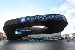
The Barclays Center arena is the 675,000-sf home to the NBA’s Brooklyn Nets. The design-build project features 18,103 seats, an 85-foot open canopy that spans the entrance, and an ice floor for hockey and other events. The arena will host more than 200 sporting and cultural events annually with seating capacity increases to 19,000 for concerts and family shows. It features 95 luxury suites, four party suites, two conference suites, four bars/lounges, four clubs, a restaurant and several street-level retail stores. The project was designed to achieve LEED Silver certification.
The iconic feature of the of the arena is the weathered Cor-ten steel lattice that wraps around the structure. Rows of steel panels envelop the exterior including an entrance canopy that cantilevers 85 feet over the plaza. The facade design with 12,000 pre-weathered steel panels and the canopy were added a month after the GMP package was released and two months before the first steel mill order was due. This required the team to incorporate the developing facade design while keeping pace with the original schedule. Nearly 1,000 tons of steel was added to support the facade, which also became a prominent design feature.
The distinctive arched roof spans more than 380 ft and is supported by a pair of 350-ft tied arch trusses spanning the long direction of the arena. The roof system geometry is complex, further complicated by the additional loads imposed by the outer facade system. The building lateral system and diaphragms were designed to resist thrust forces from the roof arches, which were minimized by use of the tension tie.
The arena’s location in a tight urban setting near a subway station and train terminal presented a multitude of challenges for the foundation system. To facilitate truck turnaround, a pair of truck elevators were designed to feed a below-grade loading dock with a large truck turntable. Building columns in this area were transferred using large plate girders spanning over the dock.
The project’s structural engineer provide structural models, connection samples, and full connection design, which allowed the team to produce models quickly, store large quantities of information and coordinate with the entire team. From its initial design, the project constantly pushed the limits of building information modeling (BIM). The complex geometry of the facade and the shortened schedule meant that the team needed to coordinate in a 3D environment and provide the information to the contractor in this format as well.
The schedule was adjusted frequently and changed even from hour to hour at the peak of construction. The design team consisted of staff members across multiple offices and practice areas. Managing the team’s efforts on such a large, fast moving project made coordination critical to the project’s success. Teams in Kansas City and New York designed the roof and bowl after which the two components were integrated. Construction support services teams worked on the structural models, model delivery and connection design. Erection engineering was performed in Chicago. Achieving integration of these services in a way that is seamless to the client required extensive communication, intense collaboration and careful management.
Design staff was maintained on site full-time to accommodate changes and oversee work. Weekly coordination meetings helped identify issues early on and develop solutions proactively.
MERIT AWARD
National Geospatial-Intelligence Agency, Springfield, Va.
Building Team
Owner/Developer: National Geospatial-Intelligence Agency, Springfield, Va.
Owner’s Representative: U.S. Army Corps of Engineers-Baltimore District, Fort Belvoir, Va.
Architect: RTKL/KlingStubbins joint venture, Baltimore
Structural Engineer: RTKL/ KlingStubbins joint venture, Baltimore
General Contractor: Clark/Balfour Beatty joint venture, Bethesda, Md.
Steel Fabricator: SteelFab Inc., Charlotte, N.C.
Steel Detailer: SteelFab Inc., Charlotte, N.C.
Consultant: Hinman Consulting Engineers, San Francisco
Photo: Paul Warchol
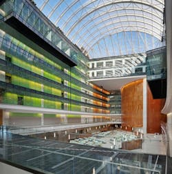
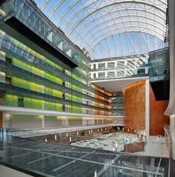
Situated on the outskirts of the Capital Beltway adjacent to the Accotink Creek stands the National Geospatial-Intelligence Agency's (NGA) 2.4 million-sf campus known as New Campus East (NCE), which has not only been designed to enhance the agency’s capabilities as one of the leading intelligence organizations in the world but also to achieve a unifying, cultural transformation. This effort to foster a unified culture is expressed in the design of the nine-story Main Office Building.
Composed of two curved 900-foot long overlapping bars around a 500-foot long central atrium and elliptical auditorium, the building’s overall form is in the shape of a lens - a fitting metaphor for NGA which serves as the nation’s eyes as the primary source of geospatial intelligence (GEOINT) for the purposes of U.S. national security, defense and disaster relief.
This defining architectural expression was accomplished primarily due to the benefits of structural steel. Steel facilitated the large bay size needed for program flexibility of the typical office, reinforced the architectural concept and imagery expressed in the transparent atrium roof, west end wall and exterior V columns, and accommodated the constraints of highly complex technical anti-terrorism/force protection (ATFP) criteria and a demanding schedule.
Managed by the U.S. Army Corps of Engineers (USACE) Baltimore District, the project has its origins in the 2005 Base Realignment and Closure Act (BRAC). RTKL Associates Inc. and KlingStubbins formed a joint venture to provide design services, including master planning and full architecture, engineering, interiors, site/civil, landscape and technology design.
At 2.2 million sf, the nine-story Main Office Building is the second largest single occupancy building in the world (after the Pentagon) and the largest federal building in the world to achieve LEED Gold certification from the U.S. Green Building Council (USGBC).
To fill the central atrium and interior of the building with light, the west end wall of the atrium was glazed with a curtain-wall system and the roof of the atrium was covered with a transparent fabric membrane. The west end atrium wall consists of a 135 foot tall by 140 foot wide curtain wall backed by a round hollow structural section (HSS) tube steel frame. Architecturally exposed structural steel (AESS) requirements were incorporated into the design, fabrication and erection of the space frame structure which served several functions. In addition to supporting the gravity loads of the curtain-wall, it supports atrium roof gravity and wind loads, and meets all mandated ATFP criteria. It also acts as a pedestrian bridge at several levels providing access and circulation between the towers.
The central atrium also serves as the main area of pedestrian circulation with a central elevator core linked by multiple bridges to each tower. Structural steel minimized the visual obstruction of these elements within the atrium and enabled them to be constructed after the towers.
The atrium roof is over 500 feet long and 45,000 sf, and consists of AESS arched steel tube members supporting an air-filled ethylene tetrafluoroethylene (ETFE) fabric roof. Although it appears clear, the custom silkscreen pattern and air filled ETFE system provides significant daylight while minimizing solar gain. Being extremely lightweight minimized ATFP-related effects, and aided in reducing the tube structure size and tonnage.
The two 900 foot wings are configured to focus on the central atrium. These dramatic spaces, as well as, the atrium’s light filled amenities create a main street for the office building community. The west end atrium wall and the atrium roof structure enhance this effect.
The unique exterior design of the main office building was achieved using signature “V” columns spaced at 40 foot on center and featured along the first and second floor perimeter, providing a separation between the visually solid base and the triangulated precast facade of the upper six floors, while also continuing the diagonals of the upper facade. In addition to providing a strong aesthetic statement, the “V” columns participate in the lateral load resisting system and accommodate alternate load path/progressive collapse design.
As with every project, the main office building had its complexities with the most obvious being its size. Using innovative Early Contractor Involvement (ECI), the USACE Baltimore District awarded the construction contract early in the design process, at about 35% design, enabling the contractor to provide valuable input to the design process and facilitate fast-tracking and value engineering. In addition, the design team delivered phased procurement packages including steel mill-order and fabrication. A committed long-term partnering process between owner, designer and contractor began early in the design process, built trust and fostered a one-team environment. That collaborative effort fostered flexible and creative, attitudes by all parties, and was a key factor leading to the project being completed on budget and six months ahead of original schedule.
Projects $15 Million to $75 Million
NATIONAL AWARD
City Creek Center Retractable Roof, Salt Lake City
Building Team
Owner: City Creek Reserve, Salt Lake City
Architect: Hobbs + Black Architects, Ann Arbor, Mich.
Structural Engineer: Magnusson Klemencic Associates, Seattle
General Contractor: Jacobsen Construction, Salt Lake City
Steel Fabricator: Ducworks, Inc., Logan, Utah
Steel Detailer: Uni-Systems, Minneapolis
Steel Erector: Uni-Systems, Minneapolis
Mechanization Consultant: Uni-Systems, Minneapolis
Photograph: Magnusson Klemencic Associates
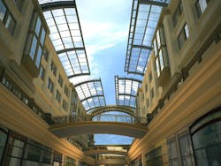
City Creek Center is the result of a plan by the Church of Jesus Christ of Latterday Saints to transform two Salt Lake City mega-blocks just south of Temple Square into a 5.5 million-sf, mixed-use development featuring retail, residential, office, and parking space. Developers wanted an urban, open-air setting, but also needed the assurance that retail businesses would be protected during inclement weather. After studying many skylight possibilities, the project’s structural engineer produced a retractable roof concept that fully met the developer’s needs.
The resulting retractable, barrel-vaulted roof is configured in two sections, each spanning one city block. Each section is 240 ft. long and 58 ft wide, with an S-shape that echoes the curve of the signature City Creek. The precision-sculpted steel and glass transparently shields patrons when closed, and disappears from sight when open; connecting nature with the areas below.
For each block, the retractable roof is comprised of three pairs of glass?covered, arching panels that cantilever 33 ft from the adjacent structures over the retail concourse. When closed, all six panels seal together and create an air and water?tight barrier. To open, the panels part in the middle and retract onto the building structure as the panels bow down out of sight from below.
Key to the bowing action are innovative whalebone-shaped ribs that support the glass roof. Each roof panel is comprised of three parallel whalebones made of curved and tapered welded steel box girders that run from the tip of each panel’s arch to the end of its back span.
The glazed portion of the three whalebone arches are joined by four purlins made of 8-in. XX-strong A106 Grade B pipe and one purlin of hollow structural section (HSS) 10-3/4 x 1-2 in. ASTM A500 Grade B tube. The purlins are designed with concealed connections that are invisible from below. The three whalebone back spans are connected with rectangular HSS ASTM A500 Grade B tubing in a K-brace configuration to provide shear stiffness between whalebones. In order to meet special finish and detailing requirements, the side and bottom whalebone girder walls were ground and filled to produce perfectly flat plane surfaces.
The whalebones were built in two sections using custom? designed fixtures and joined with a plate?welded connection to accommodate the unique geometry. The preassembled rail girders and whalebones were hoisted onto the roof, and the panels were assembled in place, stick framing whalebones, purlins, and K-braces.
Each 10.5-ton whalebone is supported by a 27-in. double-flanged steel wheel located at the bottom of the arch and two guide rollers located at the end of the back span. The wheel follows one geometric path on top of the rail girder, and the guide rollers ride an inclined track along the bottom of the rail girder. As the guide rollers travel up the incline, the roof’s cantilevered front edge dips down, causing the roof to bow down, with the wheel as the vertical rotation point.
An industrial computer located in a remote control room operates the retractable roof, which travels up to 8 ft per minute and opens or closes in approximately 6 minutes. Each panel has a unique operating sequence to prevent the panels from interfering with one another as the seals engage and disengage. The roof’s curvature, along with its complex seals and intersecting panels, made the control system the most complicated ever developed by the mechanization engineer.
NATIONAL AWARD
HL23, New York
Building Team
Owner: 23 High Line, LLC, New York
Architect: Neil M. Denari Architects, Los Angeles
Structural Engineer: DeSimone Consulting Engineers, New York
General Contractor: TF Nickel & Associates, Ronkonkoma, N.Y.
Photograph: Rinze van Brug Photography
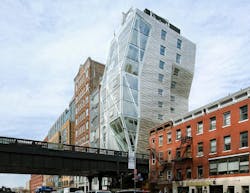
Located in Manhattan’s West Chelsea District, HL23 creates a new 14-story, 42,395-sf ultra-luxury residential building. In total, the project creates 11 condominium units, 3,585 sf of ground floor gallery space and an elevated terrace/garden area. The floor plate of the building, which is smaller at the base than at the top, owes its uniqueness to the existing elevated exposed Highline Railway - retrofitted into a city park facility - located at the eastern portion of the building lot.
Clad with a mega-panel glass and stainless steel curtain wall system, the project’s distinct form comes from the dramatic sloping of the south and east facades, creating a dynamic and undulating three-dimensional composition.
The building’s dual-lateral support system is the most intriguing element of the structure. A steel plate shear wall (SPSW) system - unique in New York City - provided the project with the benefits of increased stiffness and smaller dimension – both tremendous benefits for this site. The SPSW system is located at the elevator and stairs in combination with a full-building perimeter braced frame system. As a true sign of synergy between form and function, the architect incorporated the perimeter lateral pipe braces into the final interior aesthetic of the residences. This required special care during the design of the exposed connections of the perimeter steel diagonal braces to perimeter steel beams. It was achieved by replacing the traditional use of multiple bolts gusset plates with end plates hidden in the concrete metal deck slab for intermediate diagonal braces and with pin-end connections for end braces.
Architectural requirements played a large part in the final structural layout, and the use of structural steel was driven by three primary factors:
• Minimizing the overall weight of the structure for the capacity of the raft foundation
• Minimizing the amount of interior columns
• Providing the perimeter diagonal architectural expression.
In New York, most residential buildings are designed using a cast-in-place reinforced concrete flat plate system to maximize floor-to-floor height. However, due to the unique geometry of the building, the sprawling architectural layouts, the quality of the soil, and the hybrid gravity and lateral load system on the perimeter of the building, steel was the more economical and efficient material of choice.
Floor beams are composite with the concrete slab-on-deck; however, all of the intermediate steel beams were removed to increase headroom in the living areas. This was achieved by using shored construction in many areas with a slab thickness between 6 in. and 7 in. and varying metal deck properties throughout the floor. At the upper floors, the maximum beam/girder span was nearly 30’-0”.
Due to the building’s modest height, a SPSW system was considered both-structurally effective and visually attractive. The east-west dimension of the building is very tight, and any reduction in dimension of structure was beneficial to the floor layouts. Using 3/8-in. thick plates, instead of wide-flange brace members, freed up an extra foot of usable floor area between the columns for each wall of the system. This two foot savings was an enormous achievement in a building that is 38 feet wide.
To help speed erection, the structural engineer worked with the general contractor and the fabricator to develop a system where the perimeter of the plate was continuously welded, with three of the four sides shop welded. Prefabricated shear wall panels, with integral columns and beams, were shipped to the site and spliced in the field. This process ultimately saved a considerable amount of time in erecting the SPSW system.
The second part of the dual lateral system is comprised of perimeter brace frames on each of the elevations. In addition to lateral loads, the perimeter braced frames in many locations are part of the gravity system as well. The braced exoskeleton members are 8” diameter double-extra strong pipes at the North, South and part of the East facade; HSS 10x5 tubes on the West facade and 6x4 back-to-back angles on the remainder of the East facade. All of the pipe elements are primary architectural features and exposed on the facade and in the residences. Therefore, the detailing of these elements was heavily scrutinized. In addition to standard Architecturally Exposed Structural Steel (AESS) specifications, the nodes of the system have been designed with an exposed single 112-in. diameter pin connection. The final building aesthetic merges the strength and beauty of steel into a composite whole.
MERIT AWARD
UC Berkeley California Memorial Stadium Press Box, Berkeley, Calif.
Building Team
Owner: The University of California, Berkeley, Calif.
Architect: HNTB Architecture, Inc., Los Angeles
Architect: STUDIOS Architecture, San Francisco
Structural Engineer: Forell/Elsesser Engineers, Inc., San Francisco
General Contractor: Webcor Builders, San Francisco
Steel Fabricator: The Herrick Corporation, Stockton, Calif.
Steel Detailer: SNC, Compton, Calif.
Steel Erector: The Herrick Corporation,Stockton, Calif.
Consultant: Hassett Engineering, Inc., Castro Valley, Calif.
Photo: Tim Griffith
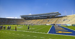
Built as a memorial to fallen alumni of World War I, California Memorial Stadium has been endured as one of the most picturesque venues in college football from its opening in 1923 to the present day. After it was discovered that the stadium was at particular risk in an earthquake, which is further exacerbated by the fact that the stadium sits directly over the Hayward Fault, the university undertook a large project to seismically retrofit as well as modernize the stadium. As a part of this project, the western stadium bowl was seismically retrofitted and modernized while keeping the existing historic perimeter concrete wall in place.
The “crown-jewel” of the project, however, is the new long-span two-story structural steel press box that floats atop the new west portion of the stadium. One of the main architectural design goals was to achieve a floating effect to the press box by reducing the number of press box supports to a bare minimum. The resulting press box structure is 375 ft long with two main spans of 100 ft long and end-span cantilevers of 33 ft.
The press box arches to follow the curvature of the existing exterior wall and is supported by four concrete cores (two at each end) and four center structural steel columns. The press box is two-stories with the first floor housing the print, radio, and TV media functions and the second floor housing a club space with views and seating facing the field as well as a dramatic 25-ft cantilevered balcony with a glass deck that faces campus with panoramic views of the San Francisco Bay and Golden Gate Bridge.
The main structure of the press box consists of a story deep space truss that is comprised of radial trusses that are supported by primary trusses which span between the concrete cores and center columns. The occupant load for the entire press box is over 1,700 people, and over 1,350 tons of structural steel were used in its construction. The overall construction cost for the project was $215 million, with the press box portion being $40 million.
Due to the close proximity of the active Hayward Fault, the seismic design of the press box and supporting concrete cores utilized several design innovations to allow for good seismic performance. The cores and press box structure were seismically separated from the surrounding bowl and allowed to move completely independent of the main bowl structure.
To alleviate large bending and shear forces and economize the design, the press box was supported on steel pins at the center of each core. These pins allow the press box to pivot on the cores and minimize damage to the steel structure building. Each 7-in. diameter high-strength steel pin is sandwiched by five 100 ksi steel gusset plates. The entire press box structure is supported on 12 of these high-strength pin assemblies.
The top level club space of the press box has a 25-ft cantilever balcony framing off the main press box space truss supporting a walkable glass deck. This balcony structure is also a space truss comprised of numerous small diameter pipe sections. This balcony truss system, which includes seismic and out of plane bracing, has several multi-member joint connections with some joints connecting up to eight pipe members. Due to the complexity of these joints, coordination had to take place in a 3D platform between the fabricators and design team.
Due to the complex nature of the site and surrounding neighborhood, there was limited space on site to allow for erection and construction of the press box. To address this issue, one of the largest crawler cranes in the country (750-ton Liebherr crawler crane with 276-ft boom and 65-ft counterweight extension) was used to erect the main press box truss in five large segments. The main space truss of the press box was assembled and welded on the playing field, adjacent to the seating bowl. Carefully selected splice locations were determined to ensure each of the five truss segments would be within the cranes capacity for weight and reach. Each of the five segments exceeded 75% of the cranes capacity and therefore were considered critical picks. The largest pick of the five truss segments was 165 tons at 160-ft reach, which took the crane to over 95% of its capacity.
The modernization and seismic upgrade of California Memorial Stadium required careful coordination and collaboration between the construction team and design team to bring this state-of-the-art press box to rest elegantly on top of the renovated stadium bowl. The stadium was able to re-open on time for the 2012 football season.
MERIT AWARD
Lee Hall III – Clemson University, Clemson, S.C.
Building Team
Owner: Clemson University, Clemson, S.C.
Architect: Thomas Phifer and Partners, New York
Structural Engineer: Skidmore, Owings & Merrill LLP, Chicago
General Contractor: Holder Construction Company, Atlanta
Steel Fabricator: Steel LLC, Atlanta
Steel Erector: Williams Erection Company, Smyrna, Ga.
Photograph: Scott Frances Photography
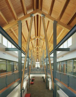
Lee Hall III is a 55,000-sf addition to Clemson University’s College of Architecture, Arts and Humanities in South Carolina. The building houses academic programs in architecture, art and planning, faculty offices and student workspace. Conceived as “a building that teaches,” Lee Hall III encourages informal learning through observation of its energy efficient design and exposed functional and structural systems. Lee Hall III has been awarded LEED Gold certification by the U.S. Green Building Council.
Nearly all of structural steel components in Lee Hall III are the direct manifestation of the architectural expression. This building is an open double-height space, 35 feet tall, housing a secondary internal structure of mezzanines and bridges. The structures roof is comprised of a light-weight composite concrete deck structure supported by exposed W14 steel beams. The roof rises four feet in a gentle arc to drain a planted green roof, which is punctuated by 25, 7-ft diameter skylights directly above “column trees.”
The “column trees” consciously draw attention to the structural steel; they are comprised of 10.75-in. diameter seamless steel pipes with 1-in. thick walls and 4 curving “arms” built out of flat 1.25-in. and 1-in. thick steel plate. The unusually thick-walled pipe columns (ASTM A106 pipe typically used in oil and gas-line construction) allow remarkably slender columns and enhance their dramatic elegance. The four curving “arms” at the top of each column tree support lines of continuous W14 steel beams and allow the roof directly above each column to open into a skylight.
The north and south facades of Lee Hall III are comprised of a custom insulated low-iron glazing which spans floor to roof. By directly supporting the glazing on structural steel members (in lieu of conventional aluminum extrusions), the designers developed window walls of exceptional slenderness with minimal and elegant detailing that is consistent with the aesthetic look of the primary structural steel frame.
The lateral systems for Lee Hall III, consist of exposed “X” braced pre-tension cables on the north and south facades and back-to-back WT ordinary brace frames in the east and west walls. Beyond the window walls on the north and south faces of the building, a row of super-slender “Y” column supports a steel trellis of exterior exposed W6 steel beams and perforated metal panels. Each “Y” column is fabricated from 4.5-in. diameter hollow structural section (HSS) steel tubes and is up to 35 feet tall.
Nearly all of the structural steel in Lee Hall III, functions as both a load-carrying functional system and a sculpturally expressive medium. But perhaps what is arguably most remarkable about its use of structural steel is that the highly and expressive character was achieved without any expensive or unconventional fabrication techniques, special finishes, exotic connections, nor the higher tolerance “AESS” designation typical of this type of construction.
Instead, the team worked closely to refine conventional simple connections and fabrication techniques that could be built by any steel fabricator without undo expense. All connections were fully detailed in the structural drawings so the alignment, appearance and architectural character could be evaluated and refined prior to the shop-drawing phase, thereby eliminating the fabricators connection engineering time and costs. Although the structure features a curving, warped roof, no curved steel was used in the building’s frame -- the geometry is a series of simple faceted arcs which nearly matches a true curve. Variation in arc radii requires the metal deck to warp slightly as it spans. The structural drawings clearly and simply convey the geometry in two-dimensional plans, elevations and details without the need for three dimensional modeling or the use of digital files.
Further cost-reduction was achieved by responding to the fabricators concerns regarding the blanket designation of “Architecturally Exposed Structural Steel” (AESS). Rather than simply applying this requirement to all of the exposed steel, the architects and the engineer identified only those aspects of AESS that were critical to the project’s success, and defined exposed painted structural steel requirements specific to the job. Remarkably, all the architectural steel in Lee Hall III was fabricated and detailed no differently than conventional structural steel.
Projects Less Than $15 Million
NATIONAL AWARD
El Dorado Conference Center, El Dorado, Ark.
Building Team
Owner/Developer: El Dorado Economic Development Board, El Dorado, Ark.
Architect: Polk Stanley Wilcox Architects, Little Rock, Ark.
Structural Engineer: TME, Inc., Little Rock, Ark.
General Contractor: CDI Contractors, Little Rock, Ark.
Photo: Timothy Hursley
Successful architecture tells the unique story of a specific place, combining history with future aspirations to create a timeless quality. El Dorado, Ark., is not a sleepy southern town, but home to the world’s eighth largest oil company, which was created with the discovery of oil in southern Arkansas at the turn of the last century. As oil in Arkansas was exhausted and related industries branched out globally, a city that reached 40,000 people had shrunk to 19,000 in recent years.
To reverse this trend, Murphy Oil implemented a stunning proposal, the “El Dorado Promise,” guaranteeing every high school graduate with good grades earned a free college scholarship. The new influx of families interested in the promise created the need to attract industry and a climate for renewed civic pride, a new Boom Town. The community implemented a series of public projects to increase exposure, including The El Dorado Conference Center, which is half public meeting space and half college student services center.
Drawing from its greatest industries of past and present to the educational advancements of tomorrow, the EDCC creates a memorable architecture intended to help propel El Dorado into a regional meeting destination.
Without the flexibility of steel, however, the unique story of this place would have been impossible to tell. The conference center weaves time, place, and story together, closing a gaping hole in the urban fabric between town and college, while serving as a beacon for the renewal of Arkansas’ original Boom Town.
Located between a historic, thriving downtown square and South Arkansas Community College, the site links “town to gown.” The square and college also influenced a building party of two naturally lit public halls, one on the path to downtown, the other to the college academic quad. These interior streets work like the town square, lined with a cafe?, bookstore, and public/college meeting rooms, while serving as galleries for the college and art center. The great halls intersection serves as the living room of the community as well as “college central” for student services.
The key component of a design philosophy of celebrating the industry is the honest expression of the steel structure building, and the craft of its detailing instead of the typical applied ornamentation. Every steel column, beam, bolt, and connection is exposed in the same functional fashion as would be seen on oil derricks and the steel bracing and platforms that adorned them. Student lounges float on upper level platforms with catwalk-like bridges connecting departments. Students can see, and be seen, sitting above the public paths.
The main public hall is a repeating cross section of a derrick’s shape and bracing, creating a soaring cathedral like space, capped with a wood shed that recalls the long timber mills of this forested region. The repeating structural rhythm and vertical thrust of the naturally lit space is a subtle nod to El Dorado native son architect, Fay Jones – the spirit is there without attempting to replicate the master’s work. Steel plates and channels are carefully layered to create memorable elements in a collegiate gothic manner. Wood is inlayed in bracing channels as stiffeners creating an elegant, yet simple, expression of function.
A great brick arch that spans the entire cafe/book store sits adjacent to the actual steel structure, like a masonry ruin held in place by the preeminent construction method of today – a steel structure.
A large steel bridge arch that runs the length of the public hall supports the suspended auto court canopy, reflecting the steel arched roof of the campus gymnasium (an old armory) across the street. What appear to be lime stone columns, like the town squares courthouse, are actually sun control fins, stopped short of the roof, to honestly express the lighter steel structure beyond, which allows the roof to float above. Where wood beams are used, they are still clearly supported by the steel structure.
MERIT AWARD
Twilight Epiphany (James Turrell Skyspace at Rice University), Houston
Building Team
Owner/Developer: Rice University, Houston
Architect: Thomas Phifer and Partners, New York
Artist: James Turrell
Structural Engineer: Skidmore, Owings & Merrill LLP, Chicago
General Contractor: Linbeck Construction Group, LLC, Houston
Photo: Paul Hester
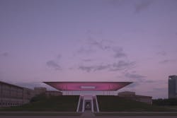
The Twilight Epiphany, James Turrell Skyspace at Rice University is a permanent outdoor experiential art installation consisting of a 72’x72’ outdoor roof atop a berm-like, two-level, below-ground viewing gallery. The Skyspace was conceived by artist James Turrell to create an atmospheric experience integrating light, sound and space that complements the natural light present at sunrise and sunset. Additionally, the Turrell Skyspace is acoustically engineered for musical performances.
The use of structural steel on Skyspace allowed the artist and design team to push the outer limits of cantilever span and slenderness, all the while concealing the structure to give the impression of a roof almost magically floating in the air. The slenderness of the columns, combined with the huge cantilevers and sight lines which hide the structural depth, create an impression so dramatic that visitors are often puzzled by how the roof stands up. The roof structure as envisioned by the artist could only have been realized with structural steel.
Visitors experience the Skyspace initially from a distance, and later by passing through tunnels into the main lower viewing area, where they can sit on granite (air-conditioned) benches and peer through the bottom surface of the roof. The lower roof surface serves as a palate upon which ever-changing hues of light are projected to alter one’s perception of the surrounding sky as viewed through a 14’x14’ oculus in the center of the roof. The project has received wide-spread critical acclaim and, perhaps more importantly, inspires delight and wonder in its visitors.
The structural system for Skyspace is comprised of a 72’x72’ octa-symmetric, tapered, cantilevering frame supported by eight slender, 6-in. diameter HSS steel cantilevered (flagpole) columns. Two concentric rings of steel girders support a series of tapered double cantilevers which reach out to the inner and outer roof edges. The lateral system consists only of the eight cantilevered columns. The tapered steel roof framing is fabricated from deconstructed, then built-up and tapered, W18 and W24 sections, HSS 5x3 perimeter tubes, and tapered stiffener plates, which reach beyond the primary beams out to the edges of the roof.
Minimizing the depth of the roof framing and aggressively tapering the steel was critical to the project, because the artist carefully calculated site lines to ensure that none of the top roof surfaces are visible when viewed from the ground. The fixed restraints on the framing depth and profile, together with the large cantilevers (nearly 25 ft along the diagonals) made designing and detailing the steel framing challenging. The tapered steel beam geometry was perfectly determined to follow the upper and lower roof slopes, with a consistent and small offset from the final surface. In addition to tapering the steel wide-flange sections longitudinally, the top flange of beams perpendicular to the roof slope is canted at the same angle as the top roof surface. The steel was squeezed within a very tight architectural package, with very small tolerances.
The tapered roof geometry continues beyond primary steel several feet until the upper and lower roof surfaces meet in a “knife edge.”
For the last 2 to 3 inches of the cantilever, there is so little depth that a tapered steel plate with stiffeners is first used; and as the depth decreases, only a flat horizontal plate extends about a foot further, until finally the architectural top surface of the roof transitions to a painted steel plate that forms the final foot of the cantilever. The outer edge of this 5/16-in. painted plate was sharpened to enhance the crisp appearance of the edge. The high-performance plaster lower surface of the roof extends all the way to the tip of the knife edge. The detailing of a seamless transition from primary steel into an exposed architectural surface that is simultaneously a structural cantilever was one of the project team’s greatest challenges.
Designing the structural steel to closely match the architectural roof profiles required close coordination with the technical architects and full detailing of all connections, primary and secondary miscellaneous steel members alike. The geometry of all steel and connections were fully specified in the structural contract drawings, leaving no interpretation to the fabricator.
MERIT AWARD
The Corner Condominiums, Missoula, Mont.
Building Team
Owner: Eric & Cheryl Hefty, Missoula, Mont.
Owner’s Representative: Eric Hefty & Associates, Missoula, Mont.
Architect : Eric Hefty & Associates, Missoula, Mont.
Structural Engineer: Apex Engineering Services, Inc., Missoula, Mont.
General Contractor: Eric Hefty & Associates, Missoula, Mont.
Photo: Mark Bryant Photographics
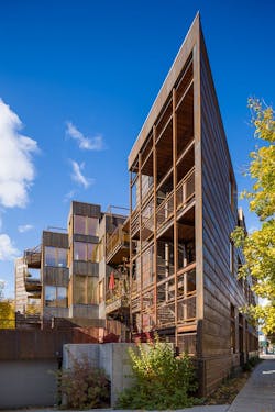
With its steel frame and weathering steel exterior, The Corner Condominiums corners the market on cool elegance in Missoula, Mont. Clad in distinctive weathering steel panels, the development, an urban infill project on a triangular site near downtown Missoula, is a fitting capstone at the end of the linear commercial area known as the “Hip Strip.”
“Because of the constraints of the site and program, we didn’t even consider any other structural system but structural steel,” says Eric Hefty of Eric Hefty & Associates, the local owner and architect of the mixed-use multifamily residential and commercial/retail development completed in the fall of 2011. The three-story project includes 7,822 sf of residential space on floors two and three with 4,900 sf of commercial/retail on the first floor.
A subtle influence on the vision for the distinctive steel-framed project was a visit the project’s developer and architect made years earlier to Bannack, a celebrated Montana ghost town. The image of a steel clad sidewall of a building that had weathered to a beautiful rust-colored patina sitting in great contrast to the monochrome gray color of the rest of the town lingered long in his memory.
But many factors lead to making structural steel the material of choice for the project:
• Constrained site - Zero lot lines combined with a complex building shape that included multiple staggered floors presented complex construction and erection challenges. Accurate off-site steel fabrication and mostly bolted connections eased the erection process. Building the steel structure “around” a wheeled crane minimized the traffic disruption.
• Narrow footprint - Three steel moment frames and four rigid frames were designed for horizontal loads created by the full use of the triangular site for underground parking, the zero lot lines, and the building height of three to five floors above the parking.
• Height limit - The height limit imposed by the city required the design team to squeeze the floor-to-floor height to a miniscule 8’-10” at the four levels of bedrooms. The steel frame allowed designers to “coffer” the ceilings to gain height. The split levels allowed the team to have high ceilings in the living, dining, and kitchens, with lower ceiling heights in the bedroom and bath areas.
• Roof support - Green roofs with heavy dead loads required structural steel framing.
• Compatibility - The steel structure was a compatible fit with the Cor-ten steel exterior skin of the building.
• Sustainability - Structural steel contributed heavily to the “green” requirements of the project, including 89% recycled content and multicycling capability to be reused or reclaimed and recycled into another product of equal or greater strength and quality at the end of its useful life.
MERIT AWARD
Sierra Bonita Mixed-Use Affordable Housing, West Hollywood, Calif.
Building Team
Owner: West Hollywood Community Housing Corporation, West Hollywood, Calif.
Architect: Tighe Architecture, Santa Monica, Calif.
Structural Engineer: Gilsanz Murray Steficek, New York
General Contractor: Parker/Sarg Industries, Pasadena, Calif.
Consultant: Castle and Gray Intl. Inc., Malibu, Calif.
Photo: Art Gray
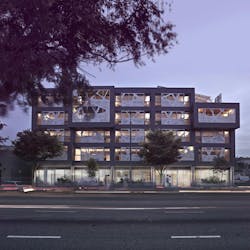
Sierra Bonita is a 50,000-sf, five-story, mixed-use affordable housing structure located in West Hollywood, Calif. It was commissioned by the non-profit West Hollywood Community Housing Corp. (WHCHC). The building is the pilot project for the city’s Green Building Ordinance, one of the first programs of its kind in the nation.
In a market sector that is accustomed to cutting corners and settling for boiler-plate design, the project successfully integrates affordability, sustainability, and style. This integration is most apparent in some of the buildings most visually striking elements – including its use of exposed structural steel -- and can be found in the courtyard’s eccentric pink fiberglass wall.
The building’s 42 one-bedroom apartments are set aside for low-income residents with special needs, including the elderly, disabled, and those diagnosed with HIV/AIDS. The ground floor provides office spaces for WHCHC and other non-profit groups, as well as retail space. Parking is provided at the basement and ground floor levels of the project.
The perimeter columns of this 112’x100’ building are spaced at 20 feet. To allow for the various uses, the building was designed with only four interior columns from the ground floor up. At the courtyard, floor beams connect to 60 foot long girders, which carry the forces back to columns at the corners.
Zoning restrictions limited the building height to a maximum of 50 feet. Typical apartment floor slabs are 11?2-in. metal deck with 41?2-in. normal weight concrete slabs which span 20 feet and work compositely with the W24 steel beams. These beams are cambered and span 43 feet, from the courtyard to the perimeter walls. The slab has extra reinforcing to allow the steel beams to align with partitions between units which results in apartments with higher ceilings. The deck was shored to control deflections under the wet weight of the concrete. The roof framing is lighter, as the deck supports no concrete – minimizing seismic loads and material use.
The ground and second floor slabs are more traditional, 3-in. metal deck with 31?2-in. normal weight concrete slabs spanning up to 11 feet to composite beams and girders. The second floor supports an outdoor bamboo garden and apartments.
The distinctive pink fiberglass wall at the entrance of the courtyard resembles a series of intersecting shards and is in fact based off of the eccentrically braced steel frame. This frame forms a component of the lateral resistance system in the north-south direction. It utilizes a variety of wide flange beams and tube steel bracing sizes to adequately express the randomness desired for the architecture.
In addition to the eccentrically braced frame, for north-south stability, a concentrically braced frame runs along the east fac?ade, while two segments of a concentrically braced frame run along the west fac?ade. The concentrically braced frames are comprised of W16 beams, W12 columns and tube steel braces ranging in size from 6x6 to 12x8.
For east-west stability, moment frames along the north and south faces of the building utilize W18 girders spanning 20 feet to the strong axis of W14 columns.
The building was originally designed to meet the 2001 California Building Code and later modified during construction to meet the requirements of the Los Angeles Amendments.
Canopies at the roof cantilever out and down past the north fac?ade to support photovoltaic panels, which framed out in tube steel and provide energy for the building.
MERIT AWARD
Solar Canopy, Chicago
Building Team
Owner: Chicago Park District, Chicago
Architect: Adrian Smith + Gordon Gill Architecture LLP, Chicago
Structural Engineer: Thornton Tomasetti, Inc., Chicago
General Contractor: Carbon Day Automotive, Chicago
Photographer: Steinkamp Photography
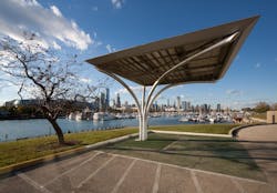
The Solar Canopy is an 11-foot-tall prototype structure consisting of 6,000 pounds of architecturally exposed structural steel (AESS). It is designed to harvest solar energy for use in powering electric/hybrid vehicles. Conceived by Carbon Day Automotive to promote sustainability initiatives in Chicago, the structure was unveiled in a temporary location in Douglas Park as one of the focal points of the International Olympic Committees visit to the city during the selection process for the site of the 2016 Olympics.
Owned by the Chicago Park District, the canopy found its permanent home on Northerly Island near the city’s museum campus and has been actively charging electric vehicles. With a construction cost of $67,000, the structure employs a cost-efficient, aesthetically pleasing and sustainable design that was achieved through integrated structural solutions, streamlined fabrication, and simplified coordination.
The canopy seamlessly blends into the background of any park and artistically complements neighboring buildings. The elegant design includes a tree-like steel superstructure that can support up to 900 pounds of solar equipment, a 300-sf canopy featuring photovoltaic panels, and a subterranean concrete foundation anchoring the structure to the ground. The prototype design is adaptable to integrate a range of photovoltaic technologies at varying orientations, providing sustainable solutions to any location around the world. The team aimed to create a flexible design that could accommodate a single structure or multiple structures linked back-to-back, creating a shaded corridor for users in the interstitial space. In large-scale applications of the solar canopy, parking lots can be converted into giant plug-in charging stations, with the possibility of surplus energy being donated to the power grid. Bolstering its sustainable appeal, the structure has the potential to collect, store, filter and reuse rainwater to irrigate adjacent agricultural or park lands.
All of the canopy’s components and connections provided a cost-efficient structural design without compromising the architectural aesthetics. To achieve this solution, the smallest diameter pipes possible were bent with compound curves. The slender pipes were visually preferred both for a graceful appearance and to limit encroachment on parking spaces. 3D CAD and 3D analysis were used to design the complex curves that give this structure its tree-like form. Since an integrated conduit is required to transfer energy from the photovoltaic panels to an underground battery pack, small access holes were provided at the top and bottom of the pipes to conceal the electrical wiring as well as to drain water.
Bolted connections were minimized in favor of welds to achieve the architectural design intent. Because of the increased use of welds, the canopy’s structural engineer sought to decrease field work by performing as much of the fabrication in the steel shop as possible. This process helped to reduce costs and allowed for better quality control of the end product.
The canopy was shop fabricated as seven pieces that were limited in size to fit on a standard truck bed, streamlining shipping. Once on site, the base was set and the columns erected. The roof structure was delivered as two pieces and connected on the ground. The solar array was then installed and the roof lifted into position and set on the bolted seat connections found at the tops of the columns. The connections were designed so that the roof structure concealed the bolts from view.
Located on Chicago’s lakefront, the canopy’s design accommodates the wind and snow loads of the city’s infamous weather, while providing an imaginative addition to the landscape. Creating the appearance of sprouting from the ground, the canopy is anchored to a concrete foundation located 1’ 4” below grade. The base connection and foundation were designed to resist a significant permanent overturning moment created by the unbalanced sprouting columns that asymmetrically cantilever from the base. To diminish deterioration of the structure, the concealed foundation allows for the heaviest of parking lot wearing surfaces, and hot-dipped galvanized steel prevents corrosion to the components exposed to the elements.
Extensive collaboration was necessary among a team consisting of nine firms to realize the unique architectural design of the canopy, while still achieving a cost-sensitive, functional structure. With only three face-to-face meetings, the majority of communication was accomplished electronically. Team members shared ideas and designs effectively through virtual communication methods, creating an efficient design process. From concept to working prototype, the solar canopy design was completed in 25 days.
As a prototype structure, the canopy is not only versatile with its ability to integrate multiple applications at a variety of sites, but it is also unique in its striking yet simplistic appearance. Whether it is used to fuel electric cars, bikes, or scooters, the canopy is a distinct addition to any landscape.
Presidential Award of Excellence in Engineering
Chelsea Piers Connecticut, Stamford, Conn.
Building Team
Owner: Chelsea Piers, New York
Architect: James G. Rogers Architects, South Norwalk, Conn.
Structural Engineer: WSP Cantor Seinuk, New York
General Contractor: AP Construction, Stamford, Conn.
Photo: Chelsea Piers
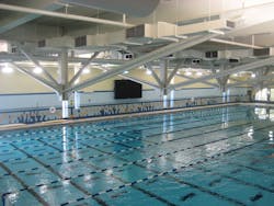
Chelsea Piers Connecticut is a 400,000-sq-ft adaptive reuse sports complex in Stamford, Conn., opened to the public in the summer of 2012. Chelsea Piers Connecticut (CPCT) features two NHL regulation ice rinks, enormous turf fields, a 20,000-sf gymnastics center, an aquatics center with an Olympic-size pool, tennis courts, squash courts, a trampoline center, a baseball/softball training area, and ancillary facilities.
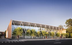
The building housing the sports facility is a 45-year-old manufacturing plant previously used by Clairol as the facility for manufacturing Herbal Essence shampoo. The adaptive reuse saved the old building from being demolished.
Although the building square footage met the Chelsea Piers requirements, the lack of large column free spaces created a potential roadblock. Professional quality sports facilities such as swimming pools, hockey rinks, tennis courts require large column-free areas in excess of 100 feet wide. This criterion required the removal of 23 columns from the building in order to achieve the column-free zones.
Achieving this economically was the principal challenge; a method to remove the existing columns while leaving the entire roof structure in place had to be developed. The solutions selected by the project’s structural engineer were extremely creative, economical and highly sustainable, resulting in reuse of the existing roof structure, limited demolition, and limited use of new materials.
The structural system devised was based upon the use of king post trusses constructed out of the in-place existing roof structure. By leaving the existing beams, which formed the top compression chords of the truss, in place and using a portion of the existing columns as the king posts, only a relatively small amount of steel had to be added to form the tension cords of the truss. Upgrading of the in-place top chord members was accomplished via composite action with the new concrete slab poured on the existing in-place metal roof deck. Steel angle members were used for the tension chords of the trusses. Although the simple and basic “off the shelf” structural members remain exposed, their aesthetically pleasing form is quite apparent. The positive effect of the forms on the facility’s architecture further testifies to the economic and sustainable accomplishments achievable from innovative engineering in which “form follows function.”
The design met all the criteria with the exception of being able to achieve a flat floor after the concrete was poured. Because the existing roof, which was supported by the new king post trusses, was slated to become additional space for the new sport facilities, a requirement existed for a very flat floor structure. The solution involved the cambering of the trusses prior to pouring the concrete slab. This was accomplished by jacking of the existing roof structure prior to the installation of the new truss members.
After the installation of the truss steel, the existing columns were cut out and removed. Upon pouring the new roof concrete, the trusses deflected precisely as designed, leaving a flat surface for the tennis courts and soccer area.
Chelsea Piers Connecticut represents an excellent example of innovative sustainable engineering for building reuse and development. An innovative design team coupled with a supportive and motivated owner, allowed this project to move forward. The result is a state-of-the-art facility serving the athletic needs of the community while forming a viable anchor business in a once abandoned industrial facility.
More on the IDEAS2 Awards.
